The Protocol Handbook
The ISO Model
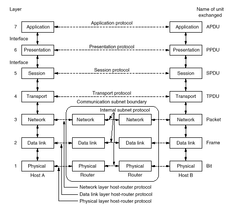
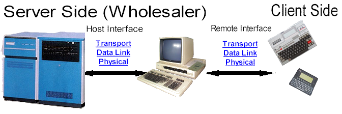
The International Standards Organisation’s network model identifies seven logical layers in a computer network (see diagram). A protocol defines the rules under which two Hosts (A and B) converse at a given layer, as represented by the horizontal dotted lines. A protocol implementation on a host at any one layer communicates only with the layers immediately above and below, as represented by the solid lines.
Once upon a time, Hosts were mainframe computers front-ended by Interface Message Processors (IMPs) which were minicomputers. For our purposes, PCs may well combine these two functions, or front-end a (usually) UNIX Host.
This site describes (some of) the protocols in use at the Physical, Data Link and Transport Layers.
In all cases the physical connection at the PC is an asynchronous serial port (now also obsolete).
The description is based upon two separate models:
- Host ⇔ PC for data transfer between the Host and a local PC,
- PC ⇔ Remote for data transfer between a PC and a remote user (customer).
As these models each represent a point-to-point connection, the Network Layer and the Communication Subnet are eliminated. Where appropriate (e.g. for Electronic Order Entry), GO.EXE implements the communication subnet, internally integrating the two models on one PC to achieve Host ⇔ Remote data transfer.
Server Side (Host)
Host Physical Layer
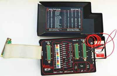
Interfaker (Serial cable tester & breakout patch)
Click image for specification.
The Physical Layer resides in Serial Port hardware and operates through a Null Modem cable directly connecting the Host to the PC. The cable transfers asynchronous 8-bit bytes as defined by the Bits/sec, Format and Terminal Port fields in the PC’s Change Settings dialog box.
- Xon/Xoff handshaking must be disabled on the Host.
- The only signal lines GO.EXE requires at the serial port are TXD, RXD and Signal Ground. It maintains DTR and RTS high at all times until shut down.
Null Modem cables
Standard pin connections are:
| Pin No (25 pin) | Pin No (9 pin) | Name | Description | Direction |
|---|---|---|---|---|
| 02 | 03 | TXD | Transmitted Data | DTE to Modem |
| 03 | 02 | RXD | Received Data | Modem to DTE |
| 04 | 07 | RTS | Request to Send | DTE to Modem |
| 05 | 08 | CTS | Clear to Send | Modem to DTE |
| 06 | 06 | DSR | Data Set Ready | Modem to DTE |
| 07 | 05 | Signal Ground | ||
| 08 | 01 | DCD | Data Carrier Detect | Modem to DTE |
| 20 | 04 | DTR | Data Terminal Ready | DTE to Modem |
| 22 | 09 | RI | Ring Indicator | Modem to DTE |
There are various methods of wiring a Null Modem cable. My preference is to connect the two ends as follows:
| TXD to RXD |
| RXD to TXD |
| RTS+CTS to DCD |
| DSR to DTR |
| Signal Ground to Signal Ground |
| DCD to RTS+CTS |
| DTR to DSR |
Some ready-made null modem cables do not make any connection to DCD, which can aggravate your troubles at the Host platform. The solution is to link DCD to DSR inside each connector.
Overrun Errors
An overrun error occurs when software fails to read a byte received by hardware before that byte is overrun by a newer byte. Old PCs (those with lower than 80386 processors) are particularly susceptible to these errors. You may reduce the incidence of this problem by:
- removing any badly-behaved resident software from CONFIG.SYS and AUTOEXEC.BAT,
- reducing the transfer speed,
- using a higher specification PC.
Host operating systems generally assume the cable transfers bytes without loss or transformation. If the transfer speed is too high for the cable length, or a network gateway is inserted in the cable, this assumption may not be valid. Host operating systems often apply their own transformations which need to be taken into account at the Data Link layer.
Host Data Link layer
Terminal emulation and DDE mode
If the PC is replacing a terminal on the Host, GO.EXE uses the PC keyboard and screen to (approximately) emulate the terminal. The data link layer consumes all terminal activity between the Host and the PC, freeing the higher layers to implement Dynamic Data Exchange (DDE). DDE is the automatic transfer of data under software control. As DDE runs on an ordinary terminal port on the Host it avoids the need for network hardware, although the serial transfer speed cannot match a network.
The user starts a DDE application (on the Host) from the terminal keyboard, then leaves the application to run to its own conclusion or requests it shut down (by pressing Esc). This may be perceived as two separate operating modes: Terminal or DDE. During DDE mode GO.EXE discards terminal keystrokes with a beep.
Two “hotkeys” on the emulated terminal keyboard may be of value. Alt+D switches between ASCII and Hexadecimal display of incoming bytes. Alt+K switches on/off the display (at top right corner) of keyboard scan codes and mouse co-ordinates (click the mouse to display its current row and column position).
Alternatively, where there is no requirement for terminal emulation, a background process on the Host may run DDE applications with GO.EXE. In this configuration GO.EXE's terminal keyboard will be turned off and the user will start the Host's background process from a Host terminal.
At any time during DDE it is possible for the Host and the PC to become out of phase with each other. For example, if GO.EXE is shut down with ALT+X when in DDE mode, the PC (but not the Host) will revert to Terminal mode when restarted. All Host transport protocols need to anticipate this possibility by ensuring DDE may be aborted cleanly at any point.
DDE Drivers
A DDE driver encapsulates the Host-specific environment so that all transport protocols are independent of the Host. The Data Link Layer implements the DDE Driver appropriate to your Host programming environment. If more than one DDE Driver is available, you specify which is to be used in the DDE field in the PC’s Change Settings dialog box.
The driver provides the Host transport layer with a standardised mechanism to exchange variable length frames (strings of printable ASCII characters) with the PC. The PC (but not the Host) may also send non-printable control frames identified in the transport protocols as ESC, FS, GS, RS and US. The standard meanings for these control frames are:
- ESC
- Terminate DDE immediately (abort any DDE in progress and revert to Terminal Emulation).
- FS
- No (cancel).
- GS
- Yes (proceed).
- RS
- (no meaning reserved)
- US
- Send the previous frame again (because an overrun error occured at the PC).
The PC activates DDE mode on detecting the start of any DDE Frame from the Host, and sends the ESC control frame to the Host upon reverting to Terminal mode.
Supported DDE Drivers
Host Transport Layer
The Host Transport Layer implements DDE application protocols.
The Host activates a particular DDE application from Terminal mode by sending a DDE frame beginning with the application’s unique four character “DDE title”.
- If the application is not available on the PC, the PC sends the ESC control frame immediately and reverts to Terminal mode.
Supported DDE Transport Protocols
- EOE
- “EOE” (Electronic Order Entry)
- FLOP
- “FLOP” (SDA Data Transfer)
- GAS
- “GAS” (Glaxo Agency System)
- TAP
- “TAP” (General File Transfer)
- WORM
- “WORM” (Document Archiving)
Debugging DDE Applications
Trace
The /Trace command-line switch will, when activated, capture all DDE activity between the PC and the Host.
- Captured frames are appended to the file HOSTLOG.TXT in GO.EXE's working directory, and will remain there until the file is deleted.
- On a live installation, be sure to switch /Trace off when not required, as
HOSTLOG.TXTcan quickly become very large. Also, delete HOSTLOG.TXT afterwards. - Only valid DDE frames are written to HOSTLOG.TXT. Faulty frames (those not complying with the active DDE Driver's requirements) and terminal activity are not recorded.
- Each completed DDE frame is written on a new line prefixed with the date and time. The = symbol precedes data received from the Host. The
-symbol precedes data sent by the PC. Non-printable characters are shown in hexadecimal within angle brackets. - When receiving data from the Host, any overruns and timeouts will be reported as <overrun> and <timeout> respectively.
- Each start-up of GO.EXE is logged (but not shut-downs).
This is a small example HOSTLOG.TXT file:
Tue 06 Jul 99 10:16:40 Started
Tue 06 Jul 99 10:17:40=<02>GAS <03><0D><0A>
Tue 06 Jul 99 10:17:40=<02>C1<03><0D><0A>
Tue 06 Jul 99 10:17:40-<1D><0D>
Tue 06 Jul 99 10:18:02 Started
In the above example, it seems that the Host failed to respond to the PC's message sent at 10:17:40 (GO.EXE must have been shut down manually in order to be started again at 10:18:02). However, it's also possible that not enough time was allowed before shut down, or the Host's response was not a properly constructed DDE frame.
Overrun
To simulate an overrun error at the PC, press the PC keyboard's letter o (in lower case) whilst in the Terminal Session. This only works when the /Trace switch and the /Kybd switch are both on.
- Simulated overruns are reported in HOSTLOG.TXT as <overrun>.
Client Side (Remote)
The Remote Physical Layer
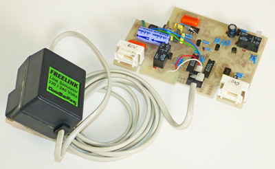
Freelink PSTN Simulator
The Physical Layer resides in Serial Port hardware and is usually a temporary connection through modems over the Public Switched Telephone Network (PSTN). At the server (wholesaler) end, GO.EXE supports a wide range of modems including the manually operated (those which cannot dial) and a direct cable (null modem) connection for in-house testing. The Telecom Session directs and reports remote communications activity through a background task known as the Communicator and is configured by the fields on the Telecom line in GO.EXE’s Change Settings dialog box.
Either end may dial a connection. Both ends then place their modems on-line and wait whilst the modems attempt to agree the best mutually acceptable data transfer connection. Either end may break the connection at any time, or some external event may intervene.
The Remote Data Link Layer
Transmission errors may occur in the Remote Physical Layer. The Data Link Layer is responsible for detecting and correcting these errors. When the receiving end detects an error in a received frame, it rejects it and sends a negative acknowledgment (NAK) to the other end, which will retransmit the frame.
- To help you assess the quality of a connection in real time, the speaker in GO.EXE's PC will grunt each time a NAK is sent or received.
Supported Data Link Protocols
GO.EXE supports the following Data Link Protocols, as selected by the client end software.
| Name | By | Characteristics | Error detection |
|---|---|---|---|
| LINK Low Level | AAH Pharmaceuticals | 7 data bits with odd parity, ASCII data transfer. Implemented by many client-end systems. | BCC |
| Gleneden | C J Trebble | 7 data bits with even or space (0) parity, ASCII data transfer. Implemented by the MediNet Corporation. | BCC |
| Async | Joe Templeman | 8 data bits without parity, Binary data transfer. Implemented within Order Entry for the Psion Series 3 and Order Entry for the Epson HX20. | CRC |
| JRC | Andy Burras | 8 data bits without parity, Binary data transfer. Implemented by MS-DOS systems from John Richardson Computers. | CRC |
| Basic | Joe Templeman | 7 data bits with even parity, ASCII data transfer. Implemented by some client-end systems. | Hashing |
Error detection schemes
| Name | Protection | Technology |
|---|---|---|
| BCC | Weak | A Block Check Character is appended to every frame, comprising a single byte being the Exclusive-OR of the preceding bytes. The receiver validates the parity of every byte and the BCC of each block. |
| CRC | Strong | A Cyclic Redundancy Checkword is appended to every frame, comprising two bytes generated from the preceding bytes by the application of a specified algorithm. The receiver validates the CRC of each block. |
| Hashing | Weak | A trailer record, holding totals for numeric data, is appended to the file. The receiver validates the parity of every byte and the totals in the trailer (a discrepancy in the latter is resolved by retransmitting the entire file). |
The Remote Transport Layer
The Remote Transport Layer executes a protocol for the exchange of messages. Most of the Transport Protocols supported by GO.EXE handle Electronic Order Entry, in which a customer Order is a message and the wholesaler's Outcome Report for that order is another message.
Supported Transport Protocols (Processes)
The client end software chooses which Transport Protocol will be used (in practice, this also determines which Data Link protocol must be used). GO.EXE's Telecom Queue Enquiry screen shows, in its Process column, the two-character code which identifies the implementation of the Transport Protocol under which an order was sent:
| Process Id | Transport Protocol | Max Lines | Multiple Orders | Data Link Protocol |
|---|---|---|---|---|
| V2, VL | The AAH LINK High Level Protocol (implemented by most PC based client end systems). Supports PIP Codes, BCL Codes, LINK Codes, case or unit quantities, back order requests on individual lines. | No limit | Yes | LINK Low Level |
| M1 | The MediNet Protocol. Supports PIP Codes, case or unit quantities, back order requests on individual lines. | No limit | Yes | Gleneden |
| P1 | The ALPHA Protocol implemented by Order Entry for the Psion Series 3. Supports PIP Codes, BCL Codes, case or unit quantities, back order requests on individual lines. Obsolete but supported. | 254 | Yes | Async |
| P2 | The ALPHA Protocol upgraded for the Psion Series 3a. Supports PIP Codes, EAN Codes, BCL Codes, case or unit quantities, back order requests on individual lines. Obsolete but supported. | No limit | Yes | Async |
| A4, A3, A2 | The ALPHA Protocol implemented by Order Entry for the Epson HX20. Supports PIP Codes, BCL Codes, case or unit quantities, back order requests on individual lines. Obsolete but supported. | 254 | Yes | Async |
| R2, R1 | The ALPHA Protocol implemented by client end Richardson MS-DOS systems. Supports PIP Codes, BCL Codes, case or unit quantities, back order requests on individual lines. Obsolete but supported. | 254 | No | JRC |
| M2 | The UNCL Protocol implemented for United Northern Cooperative Ltd. Supports UNCL Codes. This is a one-way protocol (there is no Outcome Report from the wholesaler). Obsolete but supported. | No limit | No | MSI |
| 12, 13, 14 | The Basic Protocol (implemented by some PC based client end systems). Supports PIP Codes, LINK Codes, BCL Codes, case or unit quantities, back order requests on individual lines. | 254 | No | Basic |
| US | User File Server. A mechanism for downloading binary files from Wholesaler to Customer. | Async |
All these transport protocols are half-duplex: at any time one end is sending a message and the other end is receiving it, but they may change ends any number of times during the session. In practice, the customer end sends an entire order then the wholesaler end sends the outcome report for that order then the customer end disconnects unless it has another order to send and this is supported by the protocol (Yes in the Multiple Orders column of the table).
Premature Disconnection
Bear in mind that the exchange of messages takes place over a physical path which could be disconnected at any time. If disconnection does occur unexpectedly, the Wholesaler end applies the following rules regardless of the protocol in use:
- If the customer was sending an order, that order will be cancelled in its entirety.
- If the customer was receiving the outcome report of an order, the customer will lose the remainder of that report but the wholesaler will process the order in full (ignoring the disconnection). In other words, the customer is not obliged to wait for the outcome report.
- The wholesaler acknowledges receipt of an order implicitly by starting to send the outcome report. This will always be done as soon as possible, even if the report itself is delayed, in order to minimise the critical period during line turn-around. Should disconnection occur during this critical period, the customer's software cannot determine the outcome and should warn that it is unknown. The customer may be able to infer the probable outcome by consideration of the cause of the disconnection.
To verify the PIP Code check digit:
- Take each digit (including the check digit) starting with the units position and multiply by 1, 2, 1, 2, 1, 2, 1, 2.
- Add up the resulting digits (add the digits, not the products). If the answer is an exact multiple of 10, the check digit is correct. Example:
0 0 7 3 5 8 9 4
(PIP Code 073-5894) x2 x1 x2 x1 x2 x1 x2 x1
0 0 14 3 10 8 18 4
(Products) 30
(Sum 0+0+1+4+3+1+0+8+1+8+4) Correct (exact multiple of 10)
To calculate the BCL Code check letter:
- Take each digit starting with the units position and multiply by 3, 5, 4, 6, 8 (the calculation is not defined for the remaining two higher order digits as these will be zero in currently valid product codes!).
- Add up the resulting products, divide the sum by 26 and add 65 to the remainder. Example:
0 0 1 2 3 4 5
(Product Code 12345P) x0 x0 x8 x6 x4 x5 x3
0 0 8 12 12 20 15
(Products) 67 (Sum) Remainder=15 (67 MOD 26) Check Letter = P (CHR$(65+15))
ALPHA (A4 & R2) Transport Frames
PHASE 1: Source --> Host.
Order Header
| TAG$ | 2 | Software Version Tag (ASCII 2 chars) |
| ACC$ | 5 | Customer Access Code (5 ASCII digits Right Justified) |
| PWORD$ | 5 | Customer Password (5 ASCII Alphanumeric) |
| CREF$ | 8 | Customer Reference (8 ASCII chars) |
Order Line (may be blocked to max 512 bytes per frame).
| QTY% | 2 | Quantity Ordered (Unsigned Binary, range 1:65535) (Hi byte 1st) |
| CODE$ | 4 | PIP Code & Flags or Product Code & Flags:
|
PHASE 2: Host --> Source.
TOS Item
| F$ | 1 | Flag (Wholesalers may implement additional codes):
|
| M$ | 1 | Line Number in Order File (Binary, range 0:253, 0=Header) |
| TF$ | 5 | Qty Out-of-stock (ASCII digits) |
| ANS$ | 43max | Description (ASCII chars) |
TOS Trailer
| CHR$(4) | 1 | ASCII EOT |
| TC$ | 1 | TOS Line Count+1 (0=stock not checked) (Binary) |
| ANS$ | 24max | Outcome Text (ASCII chars) |
The Source is not obliged to hold the connection after it has received the first Host frame in Phase 2; this frame confirms Order received. The Host sends TOS Item "checked" frames only if it has nothing else to send whilst waiting for the Host stock check.
The Host may request reverse interrupt (RVI) to interrupt the Source after receiving the Order Header. If the Source accepts RVI it will receive one or more message frames comprising printable ASCII characters (1 line per frame). After RVI the Source continues with the first Order Line frame (if still connected). In current practice RVI is used only to advise password incorrect (after which the Host disconnects).
Premature Disconnection. The Source should retain the Order for retransmission if it has not received any Host frame in Phase 2 (because the Host cancels incompletely received orders). After this point, to avoid duplication of the Order, the Source must not retransmit the Order. If the Source was waiting for the first Host frame it should warn that the outcome is unknown.